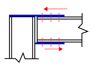
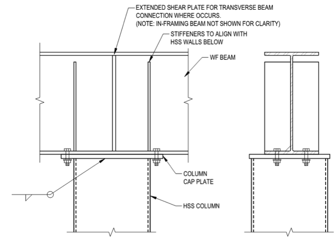
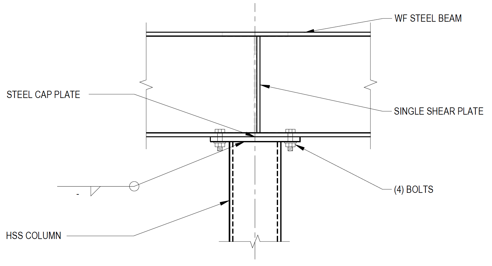
Typical column cap plate connection without stiffener plates. ExampleBase Plate with Concentric Column Load AISC ASD.
Risa Flange Plate Column Cap Plate Moment Connection Now Available
The cap plate conformed to ASTM A572 Gr.
. Figure 86431 shows a common case of a column being supported by transfer beam. Detailing requirements design procedures worked examples and. If column is wider than beam bottom flange then the cap plate is made larger to accommodate welding to the column.
The design of steel framed buildings in the UK has since 1990 generally been in. Design a base plate given that the column dead load is 100 kips and live load is 150 kips. The cap plate should be designed for bending.
If bearing strength of the column flange steel is adequate then technically you can just plop the beam right down on top of it and field weld it as StructuralEIT said. If cap and base plate splices are located away from a point of restraint special consideration should be given to ensuring adequate stiffness so that the member design is not invalidated. Design a base plate of A36 steel to occupy the full concrete area.
In terms of the projection width from the steel profile. Cal choice is usually the offset wing plates shown in Figure 4d which can be fillet welded to the column. In this case the base plate may be designed as follows.
In addition to the examples that demonstrate the use of the AISC Manual tables design examples are provided for connection designs beyond the scope of the tables in the AISC Manual. Applied to the column members and bolted to the beam or rafter especially cap plate connections in mezzanine floor structures. Steel Column Cap Plate Design.
Select a convenient width of the base plate. The wing plates must extend beyond the end of the cover plate for a length adequate to develop the load into the column. A bearing plate designed to transfer loads between two structural elements follow the same principles as discussed in the prior section however the limit state of bearing on concrete or masonry is not used.
A W10 x 49 column is supported by a concrete pier whose top surface is 19 inches x 19 inches. The beams have different flange thicknesses and thus distribute the load to the column differently. End plate beam to column flange connection 150 15.
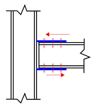
Structural steel γ M0 10 γ M1 10 γ M2 11. A W10 X 54 column of A36 steel carries a concentric load of 120 kips. Typical beam flange connection with upper column and stiffener plates.
Firstly it seems eq. WillisV Structural 2 Oct 08 2344. K1-12 doesnt care whether the member has.
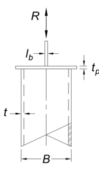
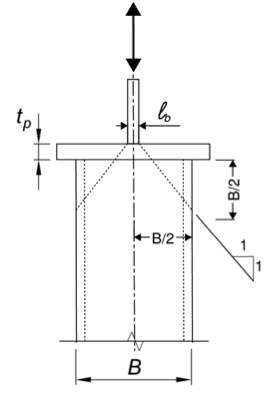
Regarding cap plate design for round HSS or pipes per AISC equations K1-11 K1-12. Width of base plate Depth of the column section 2 thickness of gusset plate 80 mm to 100 mm. Parts in connections γ M2 125 bolts welds plates in bearing DISTRIBUTION OF FORCES AT THE COLUMN BASE The design moment resistance of the base plate depends on the resistances of two T-stubs one for each flange of the column.
By equating A req and A eff calculate c. It always shows very typical cap plate connections failing by huge amounts. The column was a HSS8x8x316 which has a nominal moment strength of M n 5805 kip-in and cross-sectional axial strength of P n 2167 kips.
I thought I was just not using it correctly but I just put in the example problem 41 Beam over HSS column connection from AISC DG24 HSS Connections and Ram doesnt match up with AISCs numbers either. Cap and base or end plate column splices are covered in chapter 6 of the Green Book. The foundation concrete has a 28-day specified strength f 3000 psi.
Eurocodes - Design of steel buildings with worked examples Brussels 16 - 17. The use of an actual cap plate is more of a ease of constructability concern. This may result in a cost savings in some cases.
The location of load transfer that we are interested in. All the design examples assume. Example 11 - Design of a Column Base Plate.
Eurocodes - Design of steel buildings with worked examples Brussels 16 - 17 October 2014. The design examples provide coverage of all applicable limit states whether or not a particular limit state controls the design of the member or connection. Cover plates are plates added to the flanges of beams to increase the flexural capacity of the beam over some portion of the beam.
Base plate material is A36 steel and concrete compressive strength is 3 ksi. For ordinary column cap plates I use the following rules. In a 1969 Engineering Journal article Some Non-Conven-tional Cases of Column Design ST.
If you want just a quick check or you do not have an IDEA StatiCa license on your computer you can easily open it in IDEA StatIca Viewer and check parameters or download a DWG file. Column splice - Bearing 170. DESIGN EXAMPLE Check the column base for the design forces shown.
Although the 25 to 1 load angle model is permitted I see no guidance in the steel manual or in design guide 24 for effectively using equation K1-12 wall crippling with round tube members. The use of cover plates in regions of high moment allows the use of a section of lesser weight and lesser flexural capacity to be used as the primary beam. 50 F y 50 ksi and F u 65 ksi.
Calculate the required plate thickness. Design of Column Base Plates Typical column bases as shown below consist of a single plate fillet welded to the end of the. Example Single sided beam-to-column joint configuration bolted end-plate connection M V 15 3 IPE220 HEB140 120 60 10 30 80 30 240 4 M16 88 140.
Fin plate beam to column flange connection 159 16. Make plate as wide as the beam bottom flange. Download them and adapt to the needs of your project.
Choose from a wide range of steel connection sample projects. I Divide the factored column load by the design bearing strength of concrete and find the area of the base plate.

Designing Column Cap Plate Cc Connections In Ram Connection Youtube
Hss Limit States In Cap Plate Connections Steel Tube Institute
Risa Flange Plate Column Cap Plate Moment Connection Now Available
Hss Limit States In Cap Plate Connections Steel Tube Institute

Gusset Plate At 2 Diagonals Joint From The Bracings Category Steel Architecture Steel Frame House Steel Structure Buildings
Wide Flange Beam To Hss Column Moment Connections Steel Tube Institute
![]()
Advance Design Steel Connection
Hss Limit States In Cap Plate Connections Steel Tube Institute
0 comments
Post a Comment